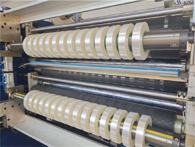
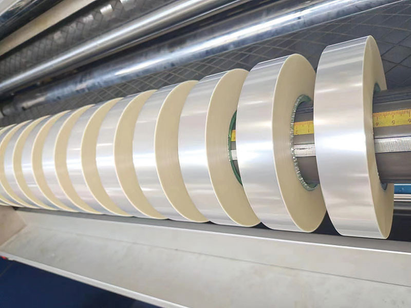
In the slitting process of PET film, uneven thickness is a common and troublesome quality problem. It not only affects the flatness and winding effect of the film, but may also lead to serious defects in subsequent printing, lamination and other processes. Many operators' first reaction is to check the raw material or adjust the unwinding tension, but often overlook a key factor – the slight deviation of the slitting knife gap. This article will explain in detail how to effectively solve the problem of uneven thickness caused by slitting through the knife gap fine-tuning method.

1. The root cause of uneven thickness: it is not only a problem of incoming materials
The reasons for the uneven thickness of PET film after slitting are complex and varied, including:
• The thickness tolerance of the base film itself exceeds the standard (but usually systematic deviations across the entire frame)
• Improper control of winding tension (manifested by tightness on the inside or loose on the outside or local folds)
• Poor slitting tool condition (worn edge, adhesive)
• Unreasonable tool gap settings (this is the most overlooked but most direct factor)
Among them, the uneven thickness caused by the knife gap problem has typical characteristics: the edge of the incision is locally raised, there are white marks on the cross-section, and the thickness near the cut edge increases significantly. If you encounter this kind of phenomenon, you can often get twice the result with half the effort.
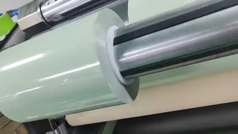
2. The principle of knife gap affecting thickness
PET film slitting is essentially a precision shearing process. A small gap (known as the gap or bite volume) is maintained between the upper and lower round knives. This gap must be just right:
• Large gaps: The film cannot be simply cut off, but is pulled and torn, and the cut edge will form a tensile deformation band, resulting in abnormal thickening or curling of the edges.
• Too small gap: The upper and lower blades interfere with each other and squeeze, causing the cutting edge to wear out quickly, and the shear force is too large to cause the film to be compressed and deformed, and the cutting edge is thinned or burrs are generated.
• Uneven Clearance: Poor parallelism or wear on one side of the cutter shaft can lead to inconsistent edge thickness across different widths of the same roll of film.
Core logic: The knife gap determines whether the shear is "cut off" or "extrusion", which is directly related to the orientation and residual stress distribution of the plastic molecular chain near the incision, which is manifested as a thickness change.
3. Standard steps of the knife gap fine-tuning method
The following method is suitable for most PET film slitting machines (upper and lower circular knife structure), and the adjustment accuracy is recommended to be controlled within the range of 0.01-0.03mm.
Step 1: Cleaning and inspection
• Shut down and cut off the air supply and power supply.
• Dip the non-woven cloth in anhydrous ethanol and thoroughly clean the upper and lower blade surfaces to remove adhesive, dust and oil.
• Check the blade for chips, chips, or obvious wear. If the blade is damaged, replace or resharpen the tool before adjusting the gap.
Step 2: Determine the reference backlash value
Recommended tool gap reference values for PET films of different thicknesses:
| Film thickness (μm) | Recommended Tool Clearance (mm) |
| 12-25 | 0.02-0.04 |
| 25-50 | 0.04-0.06 |
| 50-100 | 0.06-0.08 |
| 100-188 | 0.08-0.12 |
Note: Thinner films (such as 6μm) should have a knife gap close to 0 (0.005mm retraction after light contact), and an additional 0.01-0.02mm amplification should be required for aluminized or hard-coated films.
Step 3: Roughly adjust the parallelism of the tool shaft
In the no-load state without film:
• Place the dial indicator on the lower shaft with the probe against both ends of the upper shaft.
• Rotate the tool shaft to read the difference between the two dial indicators. If the difference exceeds 0.05mm, the horizontality of the cutter shaft or the bearing seat gasket needs to be adjusted first to ensure that the two axes are parallel.
Step 4: Fine-tune the knife position at a single point
Most slitting machines are equipped with an eccentric sleeve or adjustment screw for each set of upper knives:
1. Select a top knife that needs to be adjusted.
2. Loosen the locking screw on the upper tool holder (do not unscrew completely).
3. Use a special adjustment wrench or hexagon, turn the eccentric sleeve clockwise - the upper knife moves down, and the knife gap is reduced; Turn counterclockwise - the upper knife is lifted upwards, and the knife gap is enlarged.
4. Measure the gap between the upper and lower knives with a feeler gauge or a special gap plate for each turn of a scale (usually 0.01mm/grid).
5. After adjusting to the target value, tighten the screws and re-measure to confirm.
Experience: When measuring the knife gap, gently tuck the feeler gauge from the side of the blade to the back, feel the slight damping, and do not force the edge to deform.
Step 5: Dynamic verification and fine-tuning
• Insert a piece of waste film (width more than 300mm), and slice about 1 meter at low speed.
• Observe the quality of the trim:
◦ Smooth cutting edges without white spots → suitable knife gaps.
◦ The cutting edge is white and there are extrusion marks → The knife gap is small, and it needs to be increased by 0.005-0.01mm.
◦ The cutting edge has brushed and serrated edges→ the tool gap is large, and it needs to be reduced by 0.005-0.01mm.
• Use a micrometer to measure the thickness at 5mm, 10mm, and 20mm from the cut edge. If the thickness at 5mm is obvious (for example, more than 2μm thicker than the center), the knife gap should be increased by 0.005-0.01mm.
Step 6: Adjust the consistency of the entire frame
When it is found that the thickness of different slitting positions on the same roll of product is uneven (e.g., the left side is thick, the right side is normal):
• Check that one end of the tool shaft is sinking. Precision gaskets (0.02-0.05mm level) can be added under both ends of the tool shaft to correct the parallelism.
• Measure the actual clearance of each upper tool one by one to ensure that the clearance deviation of all tool positions ≤ 0.005mm.
4. Common misunderstandings and pit avoidance guidelines
1. Myth 1: The smaller the knife gap, the flatter the cut
Wrong. Too small a gap will squeeze the film, which will cause the edge to thicken and the blade life to plummet. Leaving reasonable gaps is key.
2. Myth 2: Adjust the knife by hand feel or visual inspection
Humans cannot perceive changes at the level of 0.01 mm. Tools such as feeler gauges, dial indicators, or laser displacement sensors must be used.
3. Myth 3: Ignore the rigidity of the tool holder
Some light slitting machines will have elastic deformation of the tool holder at high speeds, resulting in a large dynamic tool gap. At this time, it should be reduced by 0.005-0.01mm from the static recommended value as precompensation.
4. Myth 4: One knife can use all thicknesses
Each time the film thickness or variety is changed, the tool gap must be readjusted. The optimal knife clearance for different grades of PET (such as high transparency, matte, antistatic) also varies, and it is recommended to establish a process parameter record table.
5. Long-term stability measures
Knife gap adjustment is not a one-time solution, and it is recommended to establish the following management mechanism:
• Inspection of each shift: Use a feeler gauge to randomly check the gap between 2-3 tool positions and record it in the handover book.
• Large roll per change: Quickly check the appearance of the trimmed edge and fine-tune if necessary.
• Monthly maintenance: remove all upper knives, clean the tool shaft and eccentric sleeve, check for wear.
• Establish a database: Archive the optimal gap value for each PET film (thickness, grade, batch) to form a process standard.
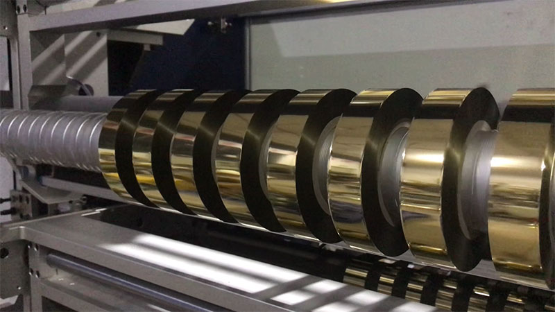
6. Case study: A successful knife gap fine-tuning
Background: After slitting an aluminized PET film (thickness 32μm), the thickness is about 3-4μm thicker than the center within 8mm from the cutting edge, resulting in bubbles during subsequent compounding.
Troubleshooting process:
• The original tool gap is measured at 0.03mm (small).
• Severe whitishness on the cutting edge of dynamic observation.
• Adjust the tool gap to 0.055mm according to the recommended table.
Results:
• The whitening of the cut edges disappears, and the cross-section is flat.
• Retest thickness: only 0.5μm thicker than the center near the cut edge, which meets the requirements.
• The problem of compound bubbles has been solved.
Epilogue
The uneven thickness of PET film slitting is often not the fault of the raw materials, but is hidden in the gap between the upper and lower knives. Mastering the knife gap fine-tuning method not only requires theoretical knowledge, but also relies on patient and meticulous measurement and verification. Hopefully, the methods provided in this article will help you quickly locate problems in your production and trade for neat, uniform slitting quality at minimal cost.
Remember a mantra: thick is clear, thin is closed, dynamic verification, and data speaks.
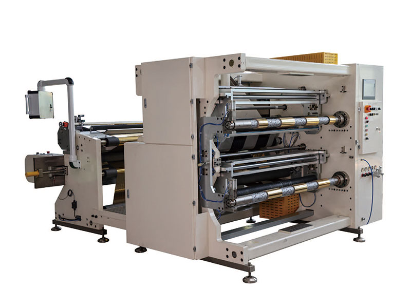 1400mm Hot Stamping Foil Slitting Machine
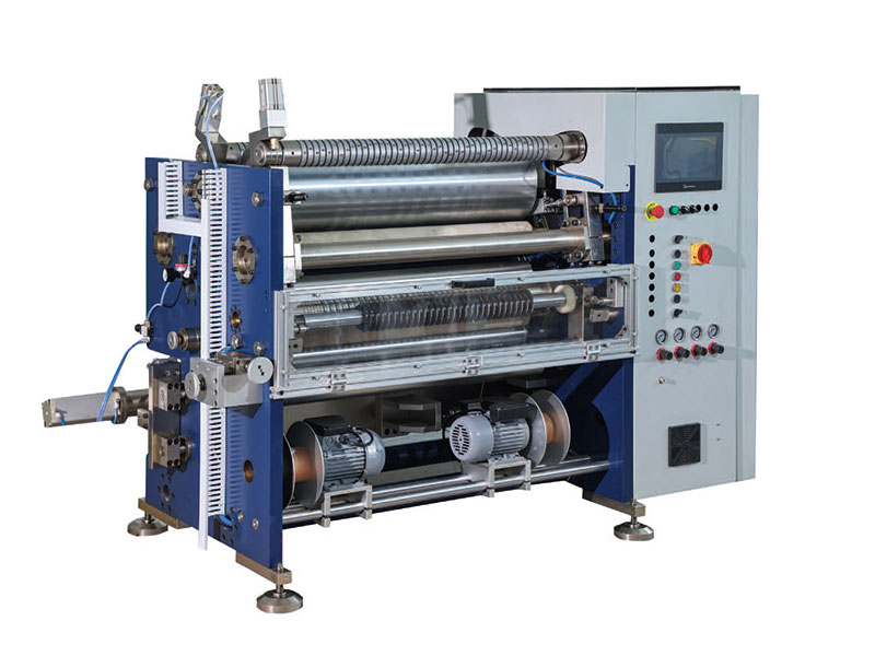 800mm Hot Stamping Foil Slitting Machine
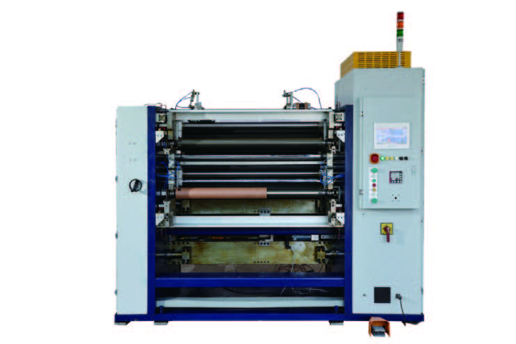 New Energy Ultra-thin Film Slitting Machine For Capacitive Film
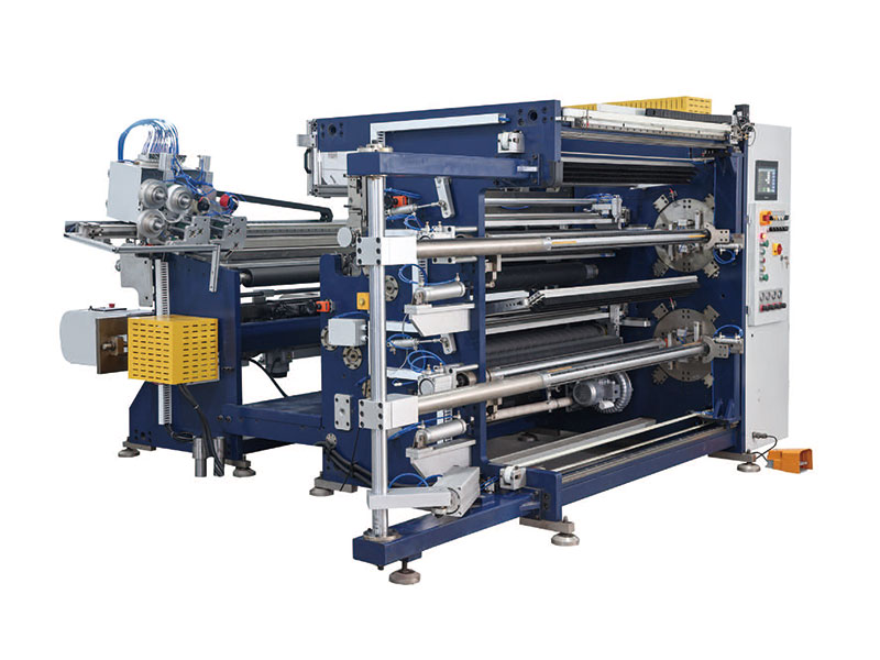 1350mm Hot Stamping Foil Slitting Machine
 New Energy Ultra-thin Film Slitting Machine For MOPP
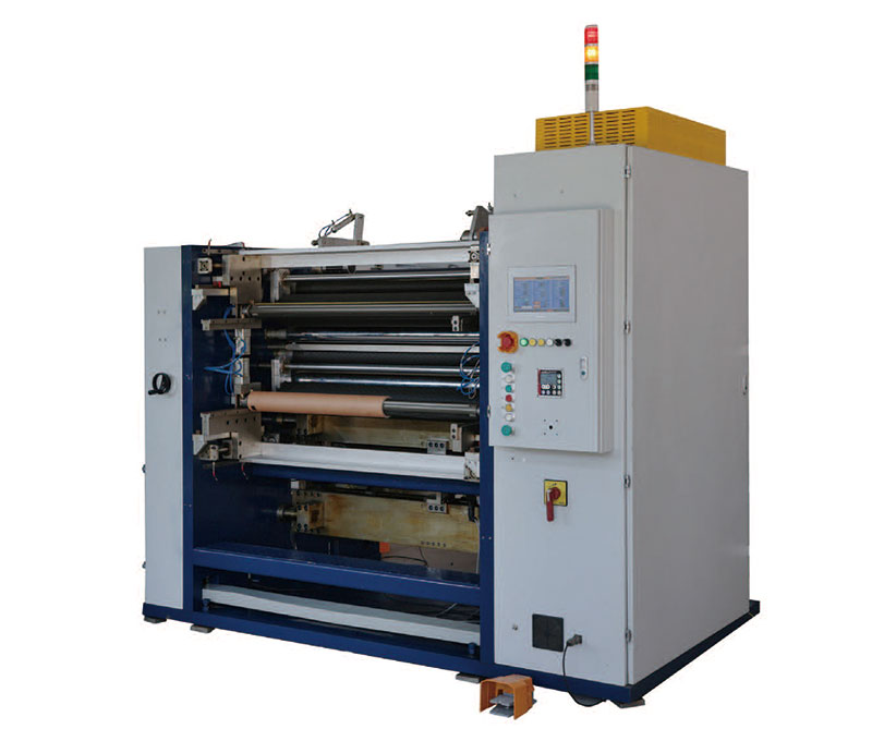 New Energy Ultra-thin Film Slitting Machine For MPET
 1400mm Copper Foil Slitting Machine


 +86 135 9951 7291
 support@delishmachine.com