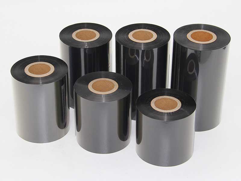
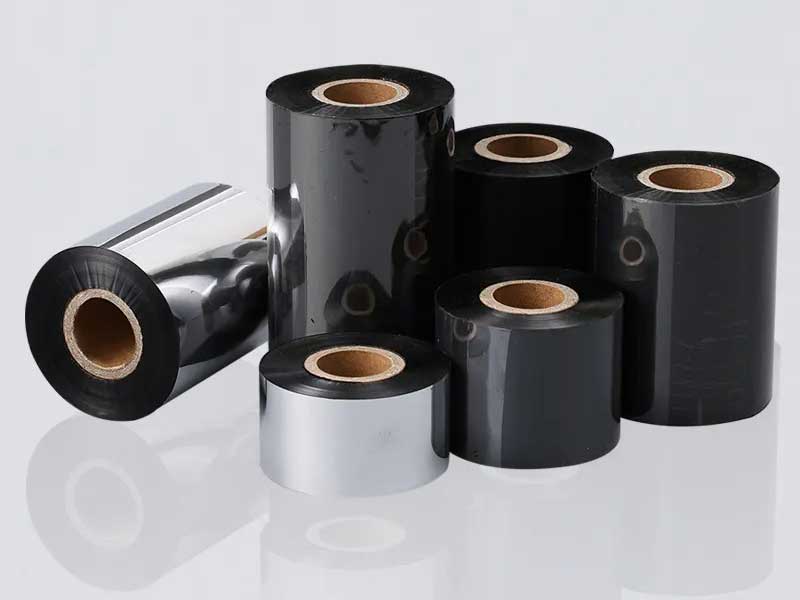
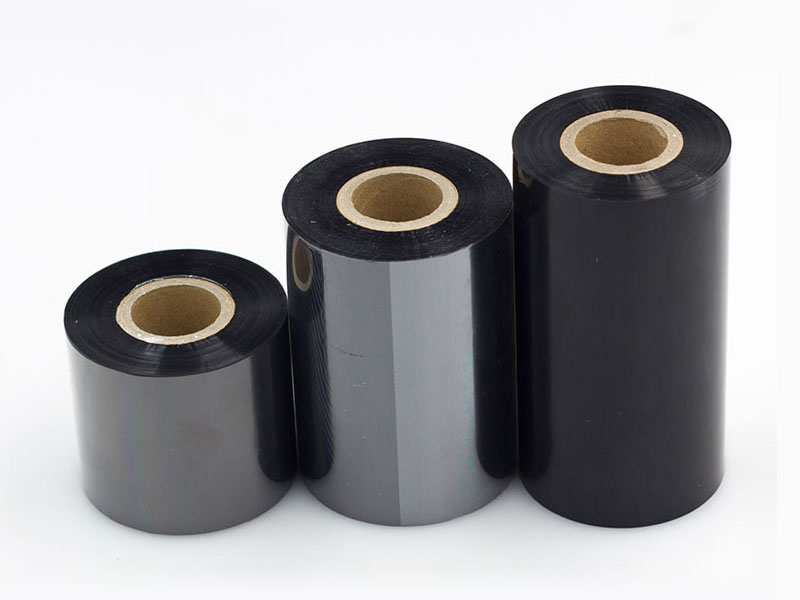
As thermal transfer printing technology develops towards high-resolution, high-density, and miniaturized labels, ribbon substrate thickness continues to decrease (from the traditional 6μm to 4.5μm or even less than 3.0μm). Thin substrate ribbons are prone to tensile deformation during the slitting process, resulting in problems such as wrinkles, deviations, printed broken needles, or character distortions. This paper systematically expounds the key technologies to solve the tensile deformation of thin substrates from four dimensions: slitting machine equipment structure, tension control, tool set process and auxiliary system.
1. Tension partition closed-loop control: from constant tension to dynamic fine-tuning
Traditional slitting machines mostly use open-loop or single-point closed-loop tension control, which is difficult to adapt to the low stiffness characteristics of thin substrates. Advanced solutions include:
1. Floating roller tension detection of the reel placement
A low-inertia floating roller set is set up after the unwinding station, and the elongation of the substrate under microtension (usually ≤ 8N/m) is detected in real time with a high-sensitivity potentiometer or laser displacement sensor. The controller adopts PID algorithm to automatically adjust the excitation current of the unwinding particle brake, so that the unwinding tension fluctuation is controlled within ±0.5N.
2. Rewinding taper tension superposition technology
As the winding diameter increases, if constant tension is maintained, the inner thin substrate will creep elongation due to continuous radial pressure. The slitting machine adopts a taper tension curve (T = T0 × [1 • k × (D/Dmax)]), which automatically reduces the tension linearly when the winding diameter reaches the set threshold, and at the same time superimposes the inertia compensation related to the coil diameter to avoid internal tightness and external loosening or interlayer slippage.
3. Isolation tension section design
The drive roller and tension detection roller are independently set up before and after the slitting knife group to form three independent tension closed loops of "unwinding section-slitting section-winding section". The slitting section adopts active traction rollers to match the linear speed of the tool set, instead of relying on the tension difference between the front and rear to drive the substrate, which fundamentally eliminates the local plastic deformation caused by the long tension transmission path.
2. Low inertia active drive and anti-stretch roller group structure
Thin substrates are extremely sensitive to roller surface acceleration, and traditional rubber pressure rollers or chrome-plated steel rollers are prone to inertial impact. Improvements include:
1. Carbon fiber/titanium composite rollers
The material of all guide rollers and traction rollers in direct contact with the carbon belt of the slitting machine is replaced with carbon fiber tube + titanium alloy end cap, and the moment of inertia is reduced by more than 60%. The roller surface is coated with ceramic or DLC (diamond-like) coating, and the friction coefficient is stable at 0.12~0.18 to avoid local stress sudden changes in the thin substrate due to surface adhesion.
2. Active anti-slack roller array
3~5 groups of small diameter (Φ30mm) active fine-tuning rollers are arranged between unwinding and tool sets, and each group is equipped with independent servo motors, which compensate for millisecond-level speed according to the feedback signals of the upstream and downstream tension meters. When the instantaneous relaxation of the substrate is detected, the corresponding fine-tuning roller actively accelerates 0.1%~0.5% to eliminate the sag; When encountering an instantaneous tension spike, it actively slows down and microbuffered.
3. Vacuum adsorption auxiliary belt
A micro-hole vacuum plate (negative pressure 0.02~0.04MPa) is installed within 200mm of the front and rear of the tool group to apply non-contact adsorption to the thin substrate. The force is perpendicular to the belt plane, and does not produce the tensile component along the strike, but it can effectively inhibit the drift and jitter of the substrate caused by airflow disturbance or static electricity, and indirectly reduce the deformation induced by tension fluctuations.
3. Optimization of low-stress slitting tool process
Circular knife or razor slitting is essentially a local shear yield process for a material, where shear forces create a radial tensile component within the plane of the substrate. Improvements for thin substrates:
1. Rotary scissors differential cutting
The independent servo drive of the upper and lower cutter axes is adopted, so that the speed of the upper circular cutter line is 1%~3% faster than that of the lower circular cutter, and the shearing mode is changed from "tearing" to "controllable slip cutting". This method greatly reduces the peak tension at the slitting point, and the height of the incision burr can be controlled within 3 μm to avoid scratching the adjacent layer due to the burr in subsequent winding.
2. Ultrasound-assisted slitting
A piezoelectric ceramic transducer (frequency 20~40kHz, amplitude 5~15μm) is integrated at the upper tool holder to generate high-frequency micro-vibration at the tip of the tool. The vibration superposition reduces the instantaneous friction coefficient of the shear area and reduces the required radial shear force by 30%~50%, thus effectively inhibiting the tensile deformation of the thin substrate along the slitting direction.
3. Adaptive tool gap adjustment
Install a laser displacement sensor to detect the upper and lower knife gap in real time, and automatically set the gap to 105%~110% of the substrate thickness according to the substrate thickness (e.g., 3.2μm PET). Too large will lead to wire drawing, and too small will cause extrusion and stretching; The adaptive system adjusts every 10 ms to avoid changing the clearance value due to blade wear or thermal expansion.
4. Environmental compensation and anti-tensile auxiliary unit
The mechanical properties of thin substrates are highly sensitive to temperature and humidity and need to be included in the control system for feedforward compensation:
1. Constant temperature and humidity closed cavity
The slitting core area (unwinding to rewinding) is enclosed in an independent chamber, and the temperature is controlled at 23±1°C and relative humidity is 50%±5%. Prevents unpredictable stretching of PET or polyimide substrates due to sudden changes in elastic modulus due to moisture absorption or temperature differences.
2. Infrared baking, softening and homogenization
Before slitting, a shortwave infrared radiation plate (wavelength 1.2~1.5μm, power density ≤15kW/m²) is installed to instantly heat the thin substrate to 8~12°C below the glass transition temperature (e.g., heating the PET substrate to 65°C±2°C). Proper heating can relax the molecular chain segments of the substrate, eliminate the residual internal stress of the previous coating process, and make the material show a more uniform strain distribution when slitting and stressing, avoiding local necking and stretching.
3. Ultrasonic non-contact tension matching
A multi-channel ultrasonic sensor is set up before winding to measure the travel speed and lateral oscillation frequency of the thin substrate surface in real time. Compare the speed signal with each driving roller encoder, and if the actual speed of the substrate is found to be greater than the linear speed of the roller surface (i.e., slip stretching), the subsequent winding torque will be automatically reduced or the pressure of the roller will be adjusted.
5. Comparison of typical case data and effects
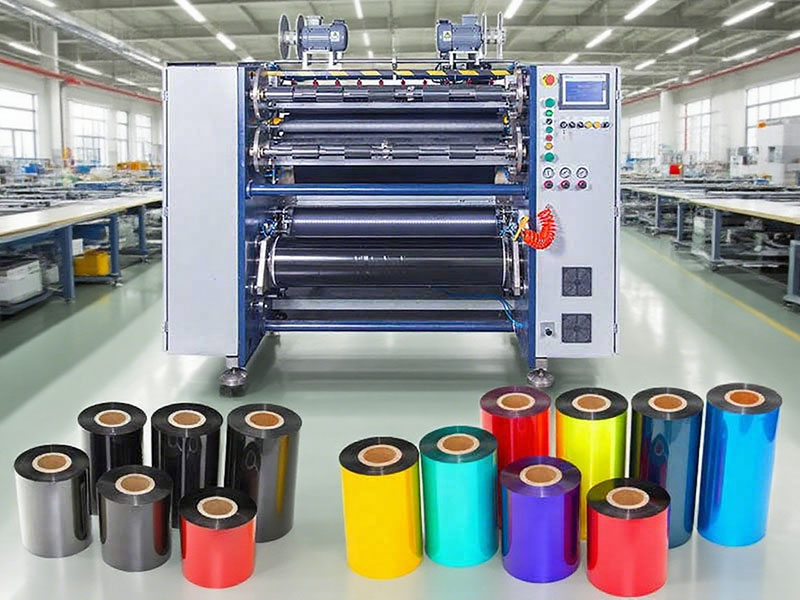
When a ribbon coating plant upgraded the 4.5μm high-density resin-based ribbon to 3.2μm ultra-high gloss ribbon, the original ordinary slitting machine caused the finished product scrap rate to be as high as 32% (the main defects were star folds on the end face and tensile deformation of printed characters). After upgrading to the above comprehensive technology (independent three-zone tension closed loop + carbon fiber roller + ultrasonic assisted slitting + constant temperature and humidity cavity), the following improvements have been achieved:
• The longitudinal elongation of the carbon ribbon after slitting decreased from 0.48% to 0.06%.
• Improved winding face flatness (end face height difference) from 0.9mm to 0.2mm;
• The length of a single roll of ribbon on thin substrate exceeds 600m (originally it could only be slitted within 300m);
• The combined scrap rate decreased to 4.5 per cent.
Conclusion
To solve the slitting tensile deformation of thin substrates of thermal transfer ribbons, we cannot rely only on the tension optimization of a single link, but must adopt a multi-layer closed-loop strategy: establish partitioned independent tension on the macroscopic level and introduce taper curves. At the microscopic contact level, the peak stress is reduced by low inertia roll set, vacuum adsorption and ultrasonic cutter. At the physical level of the material, internal stress is eliminated by temperature and humidity control and infrared preheating. By integrating these technical systems into the slitting machine, high-speed, low-distortion slitting of ribbons as thin as 3μm can be realized, meeting the stringent requirements of ultra-thin ribbons in high-end thermal transfer applications such as RFID tags and medical wristbands.

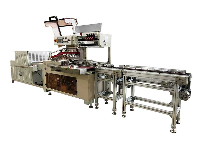 Thermal Transfer Ribbons Packaging Machine
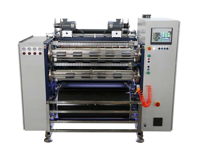 Automatic Thermal Transfer Ribbon Slitting Machine RSDS8 H PLUS
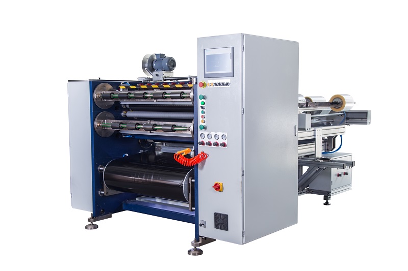 Semi Automatic Thermal Transfer Ribbon Slitting Machine RSDS5 PLUS
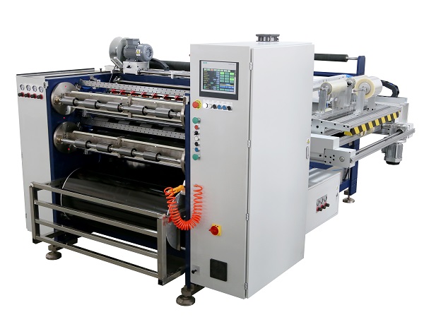 Automatic Thermal Transfer Ribbon Slitting Machine RSDS8 PLUS
 Barcode Ribbon Slitting Machine
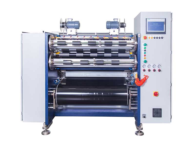 TTR Slitting Machine
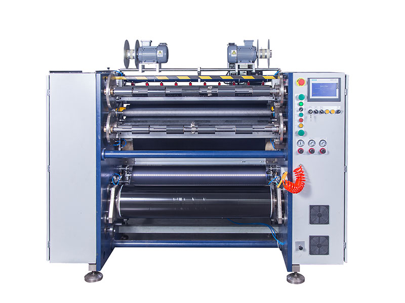 Ribbon Slitting Machine
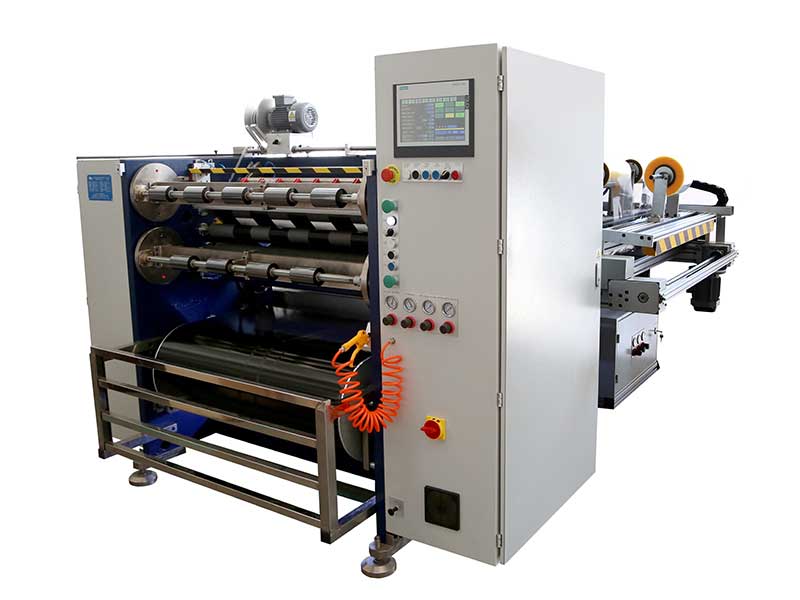 Automatic Thermal Transfer Ribbon Slitting Machine RSDS6 PLUS


 +86 135 9951 7291
 support@delishmachine.com